Navigation
Product operation
Storing and changing probe modules
NOTES: The inhibit switch in the inhibit version of the TP20 body will be automatically actuated by the magnetic field when it approaches the front of the MCR20 probe module changing rack. The minimum distance from the MCR20 probe module changing rack at which the TP20 is armed will vary with height.
When using long styli fitted to the EM1 STD or EM2 STD probe modules, do not store them in ports three or four of the MCR20 rack.
Calculating the safe clearance position
The recommended safe clearance position is located at the minimum distance from the port centre (at docking height Z) where the probe will be armed, if the probe module is attached.
The safe clearance position for any port (n) can be calculated from:
{Xn, Ys, Z} where Ys = Y – 100 mm
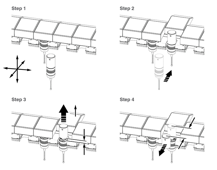
Storing a probe module
To store a probe module, carry out the following procedure:
Step 1 - Move to the safe clearance position Xn, Ys, Z for the vacant port (n).
Step 2 - Move to the docking target co-ordinate for port (n) along the Y-axis at the docking height (Z).
Step 3 - Move up to the release height Zr, where: {Zr = Z + 3 mm}
Step 4 - Withdraw from the release co-ordinate, maintaining the release height, along the Y-axis to a point clear of the port lids where the probe remains inhibited. This point is known as the ‘retract point' (RP) and has the co-ordinates: {RP = Xn, Yr, Zr} where Yr = Y – 17.2 mm
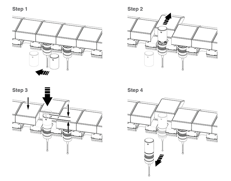
Picking up a stored probe module
To pick up a stored probe module, carry out the following procedure:
Step 1.- Move along the X-axis in the direction necessary to arrive at the RP co-ordinates for the next port required.
Step 2.- Move along the Y-axis to the release co-ordinates above the centre of port Xn, Y, Zr.
Step 3.- Move down to the docking co-ordinates Xn, Y, Z to attach the probe module.
Step 4.- Withdraw along the Y-axis to the clearance position at co-ordinates Xn, Ys, Z.
Summary of probe module changing procedure
Operation | X-axis | Y-axis | Z-axis |
|---|---|---|---|
Safe clearance position for port (n) | Xn | Ys | Z |
Move to docking position | * | Y | * |
Release probe module | * | * | Zr |
Move to retract point (RP) | * | Yr | * |
Select next port (n) | Xn | * | * |
Enter port | * | Y | * |
Move to docking position | * | * | Z |
Move to safe clearance position | * | Ys | * |
Xn = X1 to X6 as selected by the user
Ys = Y – 100 mm
Zr = Z + 3 mm
Yr = Y – 17.2 mm
* = No change to the previous setting of the axis register