Navigation
IS1-2 installation
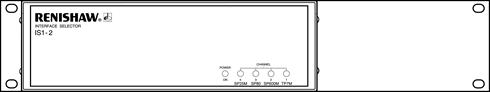
Front panel of IS1-2
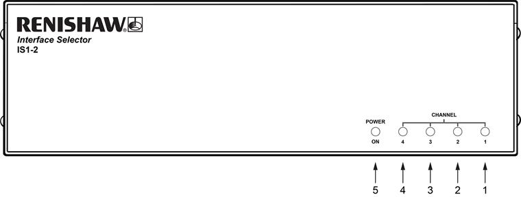
Key | Description |
1 - 4 | Output channel selected indicators |
5 | Power on indicator |
Output channel selected indicators (1 - 4)
These yellow LEDs are lit to indicate which channel is activated within the IS1-2 unit.
Power on indicator (5)
This green LED is lit when power is applied to the IS1-2 unit.
Rear panel of IS1-2
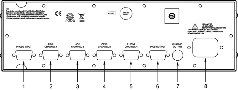
| Key | Description | Key | Description |
| 1 | Probe input port | 5 | IS1-2 output channel 4 |
| 2 | IS1-2 output channel 1 | 6 | PICS output |
3 | IS1-2 output channel 2 | 7 | IS1-2 channel output |
4 | IS1-2 output channel 3 | 8 | Mains power input |
Probe input port (1)
This 15-way high density 'D' socket is the connection from the multiwire cable to the IS1-2.
The function of each pin is dependent on the probe that is connected, but the table below indicates general connection details:
Probe input connections:
Pin | Designation | Pin | Designation |
|---|---|---|---|
1 | Uncommitted | 9 | Co-axial screen |
2 | Screen | 10 | 75 Ohm co-axial inner |
3 | 2 wire probe signal / probe ident return | 11 | Uncommitted |
4 | Uncommitted | 12 | Uncommitted |
5 | Uncommitted | 13 | 2 wire probe signal |
6 | Uncommitted | 14 | Fixed head LED anode |
7 | Uncommitted | 15 | Fixed head LED cathode |
8 | Probe ident |
Probe output port (2 - 5)
These 15-way high density 'D' plugs are the connections from the IS1-2 unit to the appropriate probe interface as specified by the programming module.
The function of each pin is specified in above.
PICS output (6)
This 9-way 'D' plug maintains compatibility with the Renishaw product interconnection systems (PICS).
As the IS1-2 is neither a probe interface or a controller the only connection that is activated is STOP.
The table below indicates the PICS output connections.
IS1-2 PICS connections:
Pin | Designation | Pin | Designation |
|---|---|---|---|
1 | STOP | 6 | Not connected |
2 | Not connected | 7 | Not connected |
3 | 0 V reference | 8 | Not connected |
4 | Not connected | 9 | Not connected |
5 | Not connected |
IS1-2 channel output (7)
This 6-way mini DIN socket can be used to give an electrical indication of which output is selected.
The electrical output levels conform to the Renishaw PICS specification, i.e. outputs 1 to 4 are normally high (+5 V) and are pulled low when the appropriate interface channel is selected.
The table below gives the pin numbers and their function.
IS1-2 channel output:
Pin | Designation | Pin | Designation |
|---|---|---|---|
1 | Channel 1 selected | 4 | Channel 4 selected |
2 | Channel 2 selected | 5 | 0 V |
3 | Channel 3 selected | 6 | Not connected |
These outputs are open collector devices with 3K3 pullup resistors and the following characteristics:
ON | 0.4 V max @ Ic = 15 mA |
OFF | Leakage current = 0.25 mA max @ Vce = 5.25 V |
Installation of programming modules
The IS1-2 comes with four programming modules pre-installed. If it is necessary to change the programming modules please refer to the 'Changing the programming modules default configuration' section below.
Default configuration
When the IS1-2 unit is received the programming modules will have been installed into the unit in the configuration as follows:
Channel 1 | Configured for TP7M |
|---|---|
Channel 2 | Configured for SP600M analogue scanning probe |
Channel 3 | Configured for SP80 analogue scanning probe |
Channel 4 | Configured for SP25M analogue scanning probe |
The respective probe and interface identification labels for the modules fitted can be attached to the front and rear panels of the IS1-2 unit.
Changing the programming modules default configuration
CAUTION: Risk of electric shock - To re-configure the IS1-2 programming modules it is necessary to remove the top cover of the IS1-2 unit. The mains power connection must be removed from the unit prior to removing the lid.
The suggested procedure to change the programming modules:
1. Remove power lead from IS1-2.
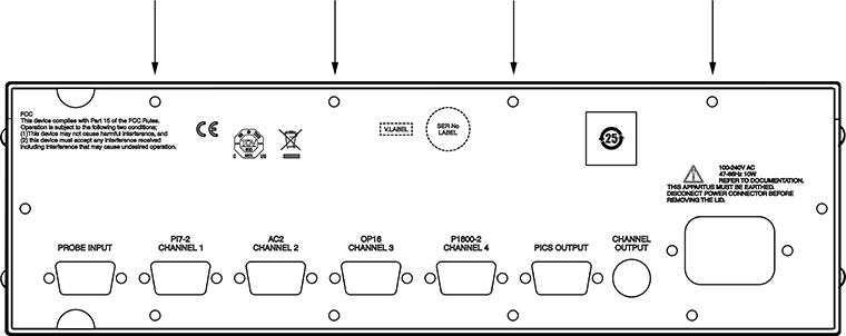
2. Remove the top panel from the IS1-2.
- This is done by removing the four screws on the top edge of the rear panel:
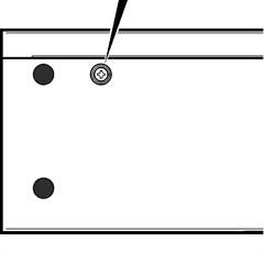
- Then remove the retaining screw on each side of the box:
3. Lift lid vertically to remove from enclosure.
- Position the IS1-2 programming modules into the required position, note the programming module orientation with respect to the IS1-2.
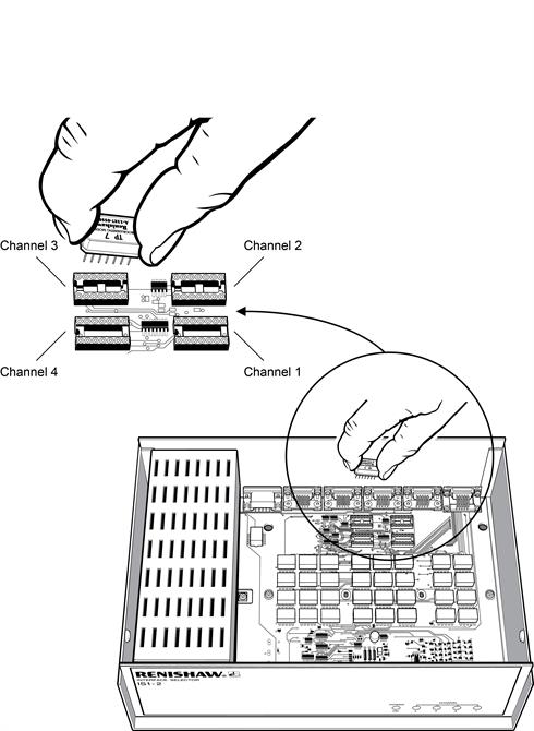
- Replace the top panel following the reverse of steps 1, 2 and 3.
NOTE: SP80 must not be used in channel 4.
Stand-alone installation
Four self-adhesive rubber feet are supplied with the unit for stand-alone use.
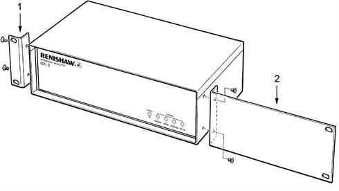
Mounting alone in a 19" rack
WARNING: Risk of electric shock - In all installations ensure the IS1-2 is disconnected from the mains supply during installation.
WARNING: Risk of thermal damage to product - Take care not to exceed the operation ambient of 40 °C around the unit. Do not install near sources of heat. Forced cooling may be required in final installation.
NOTE: In all installations use the mounting screws supplied with the equipment. Do not replace with longer screws as damage can occur.
The figure below shows the IS1-2 ready for mounting to a 19" rack.
Remove the blanking plugs from the side panels of the IS1-2 and fit the blanking panel (2) and rack mounting bracket (1) using the screws supplied as shown in the following figure.
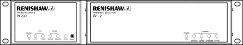
Mounting next to an interface
The figure below shows the IS1-2 with a PI 200 interface ready for mounting to a 19" rack.
System interconnection
The figure below shows schematically how combinations of probes, probe heads and autochange can be integrated into one system using the IS1-2.
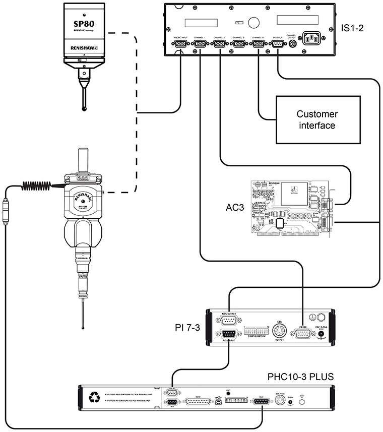
Please contact Renishaw if the system you are connecting together incorporates any of the following:
- A PI 7 probe interface that was manufactured before August 1993
- Any component of the Renishaw OP5 system, which was made obsolete during 1995
- A PI 12 probe interface
- VPI 1 or VPI 2 video probe interface
- Any non-Renishaw probes that carry the female autojoint